
In this post, I want to discuss about autonomous vehicles software stack: the common software modules, the basic control and data-flow of the software stack, and the basics of the algorithm behind each software module.
Common Architecture
The diagram below shows a general and common architecture for autonomous vehicles (AV).
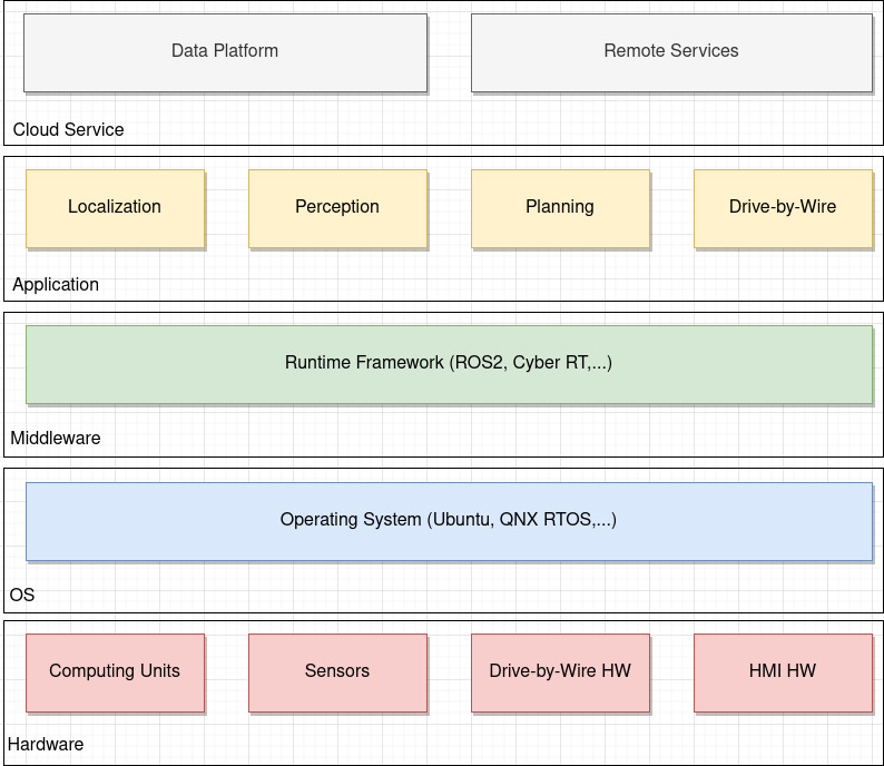
We can think it as a stack of layers:
- Hardware: This layer contains
computing unitssuch as Nvidia AGX Xavier,sensor devicessuch as Velodyne Lidars - Operating System: It can be
general-purposeorReal-time operating system(RTOS) such as Ubuntu and QNX OSs - Middleware or Runtime Framework: This layer provides general and common services, environment, and interfaces for upper layer to run on top of the below OS layer. For example, it provides a general framework for creating application tasks such as perception and planning, and communication mechanism for tasks to communicate. It also provides interfaces between application tasks and hardware such as sensors. Some examples of middleware are
Robotic Operating System (ROS)used inAutoware.AutoandCyber RTused inApollo - Application: It contains software modules for performing the autonomous driving task such as
localization,perception, andplanning - Cloud Services: This layer is optional. It can contain storing log data, vehicle remote command services
Inputs/Outputs
Roundly speaking, the inputs of an autonomous vehicles software system are:
- Point cloud data: from Lidar, radar, and IMU sensors
- 3D map data: from the mapping packages
- Image data: from cameras and Lidar sensors
Its output are:
- Velocity: as command to the vehicle drive-by-wire controller
- Angle: as command to the vehicle drive-by-wire controller
Control and Data-flow
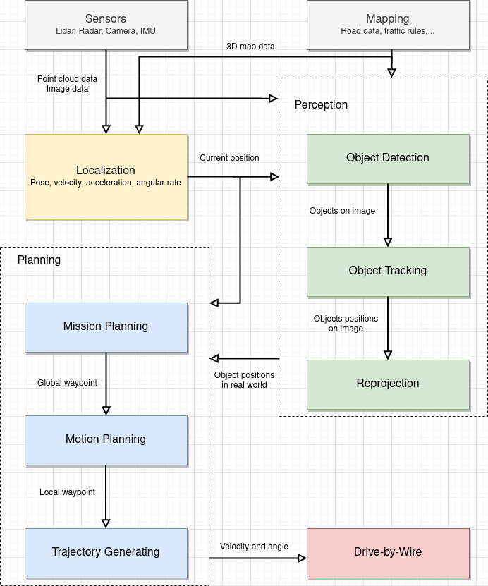
Basic control and data-flow of the (application) software stack is depicted in the following figure. Note that we loosely denote the sensor data from 3D lidar, monocular cameras, GPS/IMU, and radar by 3D point cloud and image data.
Common Modules
As depicted in the above figure, roundly speaking, an AV software stack includes:
- Sensor Inerfaces: This module is responsible for receiving
raw data from sensorssuch as 3D lidars, cameras, and radars - Localization: This module uses 3D point cloud data from 3D lidars, GPS/IMU, and mapping module to estimate the current position of the vehicle. The position may contain information about the vehicle
pose,velocity, andangular rate - Perception: This module takes 3D point cloud data, images data, and output from localization module to
detect and track objectsin the real world environment. It may alsopredict the object behavior. Finally, it reprojects to output theobject positionsin the real world. - Planning: This module takes the outputs from localization and perception modules as inputs for generating trajectories in order to compute
velocityandangleas outputs. - Drive-by-Wire: This module takes outputs from planning module as inputs to control the vehicle via the
CAN messages. - Mapping: This module provides semantic map of the environment such as the road data, traffic light information, traffic rules such as speed limit.
These are the common modules for AVs. In practice, there are additional modules such as monitoring system, task management and fault-tolerance, logging, and simulation. The details of each module will be discussed in the next posts.